J1: 2.5mm center positive barrel connector (5-15V DC)Īdditional parts added to the schematic includes A barrel jack (J1) for easy connection to a wall adapter (12V) and a screw terminal (12) to conveniently connect to the perimeter wire.C3 : 1.2nF (1000pF will also do the job).R3 (Current limiting resistor): 47 Ohms (needs to be fairly large to dissipate heat with a 2W power rating should be enough).
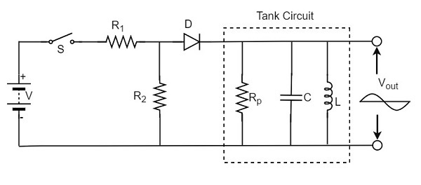
#USE TANK CIRCUIT AS TIMER GENERATOR#
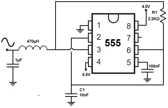
Here is the complete schematic of the generator circuit :Īs you can see in the schematic, few additional components were added and will be discussed below. Since that the 4.7KOhms potentiometer never gets to 0 or 4.7, the output frequency range will vary from around 33.5Khz to 39Khz. The theoretical lowest and highest value of the output frequency will be as follows calculated by the formula (1) : The potentiometer will help us vary the frequency of the square wave output to match the resonance frequency of the LC Tank circuit that will be discussed later on. For this, we have chosen Ra = 3.3KOhms, Rb = 12KOhms + 4.7KOhms Potentiometer and C = 1.2nF. The frequency range of the generated square wave will be between 32Khz and 44KHz which is a specific frequency that shouldn't interfere with other close devices.

The formula used to calculate the frequency of the output square wave is : A few additional components were added and discussed below. Schematic and Prototyping The schematic provided in the NE555 manual (8.3.2 A-stable operation section) is fairly complete. We do offer this nice 555 Timer Soldering Kit that will give you the opportunity to solder all the internal components of a 555 timer in a through hole package to allow you to understand the operation of this circuit in detail. Texas Instruments is not the only manufacturer of NE555 ICs, so should you choose another chip, be sure to check its manual. Referring to the NE555 datasheet for the timer, there is a sample circuit, as well as the theory of operation (8.3.2 A-stable operation). The NE555 Generates a (rough) square wave which can run the length of the perimeter wire. The arrangement of the components is as shown in the schematic below. Two resistors and a capacitor make it possible to modify the oscillation frequency as well as the duty cycle. The stable configuration allows using the NE555 as an oscillator. For our generator, we will use the NE555 in Astable configuration. One billion units are manufactured per year. This component is still used today because of its ease of use, low cost, and stability. NE555 or more commonly called 555 is an integrated circuit used for timer or multivibrator mode.

The perimeter wire generator circuit will be based on the famous NE555 timer. This way, you can add the wire perimeter detection feature to your favorite robot and keep it within an operating "zone".

The files (Schematics, Eagle Files, Gerbers, 3D Files and Arduino Sample Code) are also available for download. This tutorial explains in an easy and intuitive way to help you understand the theory, design, and implementation to make your own generator and sensor for a perimeter wire. For example, here is a video of the Robomow RS630 in action : LEGO also uses the same principle to guide vehicles along roads without visitors seeing any lines.

These days, perimeter/boundary wire is also used to create “invisible fences” to keep pets within yards, and robot lawn mowers within zones. A processing chain (amplification, filters, comparison) makes it possible to determine the position of the robot within to the wire. The robot is equipped with inductive sensors, usually based on a tank circuit (with a resonance frequency equal or close to the frequency of the generated wave) that measures the intensity of the electromagnetic field close to the ground. An alternating current of relatively low intensity and frequency between 5Kz and 40KHz flows in this wire. The robots follow a wire loop buried in the ground. Wire guidance technology is widely used in the industry, particularly, in warehouses where handling is automated. Get your own Perimeter Wire Generator and Sensor Soldering Kit here Background


 0 kommentar(er)
